
STM32F103C8T6 ARM Cortex-M3 microcontroller core board, 72MHz development system board with 64KB flash memory and 20KB SRAM, 5.3cm x 2.2cm compact PCB with Mini USB interface for power and communication, SWD debug mode ready
STM32F103C8T6
£12.68
Skip to product information

 This development board provides a ready-to-use hardware platform centred on the STM32F103C8T6 microcontroller from STMicroelectronics. It delivers a complete minimum system, incorporating essential components like power regulation, clock generation, and programming interfaces onto a compact 5.3cm by 2.2cm PCB. It is designed for engineers, students, and hobbyists seeking a practical foundation for projects utilising the popular ARM Cortex-M3 architecture, eliminating the need for initial custom PCB design for basic functionality.
 The board's functionality is defined by the specifications of its central microcontroller and supporting circuitry.
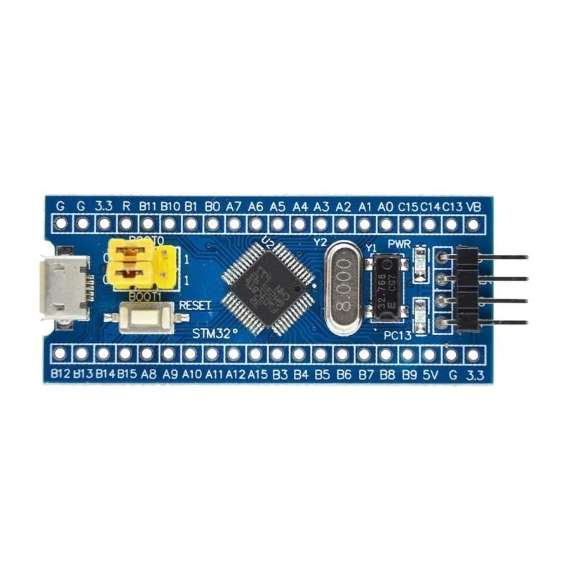
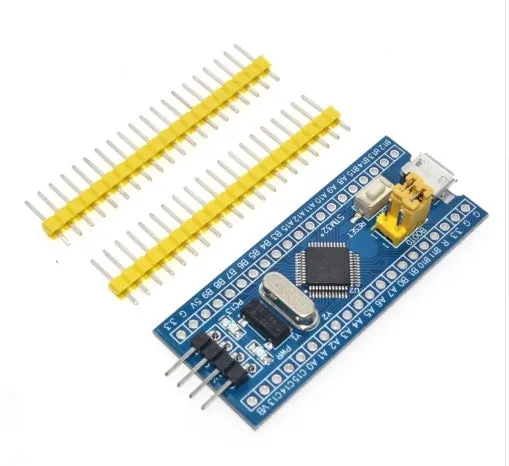
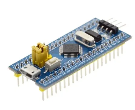
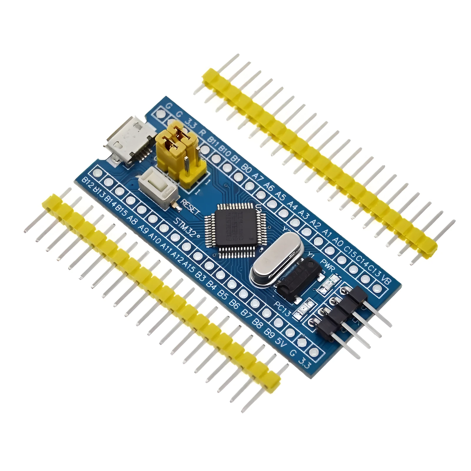 The board's layout prioritises accessibility and integration in a small footprint.
 This board is tailored to streamline the process of working with STM32 microcontrollers.


STM32F103C8T6 ARM Cortex-M3 microcontroller core board, 72MHz development system board with 64KB flash memory and 20KB SRAM, 5.3cm x 2.2cm compact PCB with Mini USB interface for power and communication, SWD debug mode ready
£12.68
STM32F103C8T6 ARM Cortex-M3 Minimum System Development Board for Compact Prototyping
Core Technical Specifications
Microcontroller and Performance
At the heart of the board is the STM32F103C8T6, featuring a 32-bit ARM Cortex-M3 core CPU. This processor operates at a frequency of 72MHz, providing substantial computational power for embedded applications. The chip is equipped with 64 kilobytes (KB) of integrated flash memory for storing application code and 20KB of SRAM for data handling during operation, offering a balanced resource set for many development tasks.Power and Electrical Characteristics
The system is designed to operate from a supply voltage ranging from 2.0 volts to 3.6 volts, which applies to both the core and its general-purpose I/O pins. It includes Power-On Reset (POR) and Power-Down Reset (PDR) circuitry, ensuring reliable startup and recovery. An on-board 4-16MHz crystal oscillator provides the precise clock source required for the microcontroller's stable 72MHz operation and accurate timing functions.Physical Design and Connectivity
Compact Form Factor and Layout
Integrated USB Interface A key feature is the on-board Mini USB connector. This single port serves a dual purpose: it can be connected to a standard USB port on a computer or a 5V USB power adapter to supply power to the entire board, removing the need for a separate power supply. Simultaneously, it facilitates USB communication, allowing the developed application to interact directly with a host computer for data transfer or device control functions.Development and Practical Application